
Troubleshooting a “no communication” issue with your 3010 Ford Fusion Hybrid Scan Tool can be frustrating. This comprehensive guide outlines common causes and provides a step-by-step diagnostic procedure to help pinpoint the problem. This article focuses on the critical role of network communication within the vehicle’s computer system.
Understanding the Ford Fusion Hybrid Communication Network
The Ford Fusion Hybrid relies on a complex network of modules that communicate with each other to control various vehicle functions. A successful diagnostic scan requires seamless communication between the scan tool and these modules. The primary network for diagnostics is the Controller Area Network (CAN).
Key Network Components:
- CAN (Controller Area Network): A robust, high-speed network used for critical communication between modules like the Powertrain Control Module (PCM), Instrument Cluster (HEC), Anti-lock Brake System (ABS), and the Transmission Control Module (TCM).
- Network Termination: Crucial for stabilizing voltage and eliminating interference on the CAN bus. Achieved through terminating resistors typically located within the PCM and HEC. A total network impedance of 60 ohms is expected with both resistors functioning correctly.
- DLC (Data Link Connector): The OBDII port, your scan tool’s entry point to the vehicle’s network.
Step-by-Step Diagnostic Procedure
Before diving into complex diagnostics, ensure your 3010 Ford Fusion Hybrid scan tool is functioning correctly by testing it on another vehicle.
1. Preliminary Checks:
- Dashboard Warning Lights: Note any illuminated warning lights, as they may indicate a malfunctioning module.
- DLC Voltage: Verify voltage at the DLC. With the key OFF, pins #6 and #14 should have battery voltage. With the key ON, these pins should show approximately 2.5 volts each, totaling around 5 volts.
- DLC Resistance: Measure the resistance between pins #6 and #14 with the key OFF. A reading of 60 ohms indicates proper network termination. 120 ohms suggests a problem with one of the terminating resistors.
- DLC Ground: Confirm a solid ground connection at pins #4 and #5.
- Fuse Inspection: Check fuses #12 (DLC power) and #22 (PCM power) for continuity.
2. Key Power and Ground Checks:
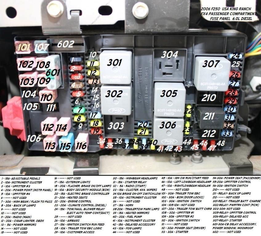
- Fuse #22 Power: This fuse supplies power to the PCM. If blown, trace back to the PCM Power Relay (relay 302) and its associated wiring.
- Ground G100 and G101: These grounds are critical for PCM operation. Inspect for damage and ensure a tight connection.
3. CAN Bus Diagnostics:
- DLC Pin Inspection: Examine the DLC connector and pins for any signs of damage or corrosion.
- PCM Connector Inspection: Disconnect and inspect PCM connector C1381a, focusing on pins 13 and 14 (CAN High and CAN Low). These connect directly to the DLC.
- Voltage Checks: With the key ON, check for approximately 2.5 volts on DLC pins #6 and #14 relative to ground. The voltages should add up to approximately 5 volts.
- Resistance Checks: With the batteries disconnected and the system “asleep”, check the resistance between DLC pins #6 and #14. The reading should be 60 ohms.
4. Module Isolation:
If the issue persists, a faulty module may be disrupting communication. Disconnect the HEC, ABS, and TBC modules one at a time, retesting communication after each disconnection. This helps isolate the problematic module.
Conclusion
Successfully diagnosing a “no communication” issue with a 3010 Ford Fusion Hybrid scan tool requires a systematic approach. By understanding the vehicle’s communication network and following these diagnostic steps, you can effectively pinpoint the problem and restore communication for accurate vehicle diagnostics. If the problem persists after these checks, consult a qualified automotive technician for further assistance.