Are you maximizing the capabilities of your scan tool? Many automotive technicians utilize scan tools primarily for retrieving Diagnostic Trouble Codes (DTCs) and examining parameter data. However, they often overlook other powerful functionalities, notably bi-directional control. The vast majority of enhanced scan tools in the market today are equipped with this feature, which can significantly streamline and enhance the diagnostic process.
Bi-directional control, in essence, refers to the two-way communication between a diagnostic device and a vehicle’s control modules. Vehicle manufacturers design their computer control systems to allow scan tools to not only request information but also to command modules to perform specific tests and functions. You might encounter bi-directional controls under various names depending on the manufacturer, such as functional tests, actuator tests, inspection tests, or system tests. Furthermore, functionalities like reinitialization and reprogramming also fall under the umbrella of bi-directional control.
This article aims to shed light on the advantages and limitations of bi-directional controls and illustrate their practical applications in automotive diagnostics. While specific scan tools will be mentioned for illustrative purposes, this is not an exhaustive evaluation of every tool available.
The scan tool itself can be considered a bi-directional device, as it inherently sends and receives data to and from vehicle control modules. For instance, when using OBD II generic Mode 1 to access parameter data, the scan tool initiates a request to the Powertrain Control Module (PCM). The PCM then responds by transmitting the requested information back to the scan tool for display. Beyond data retrieval, most enhanced scan tools empower technicians to actuate components like relays, injectors, and coils, and to execute comprehensive system tests, all through bi-directional commands.
Figure 1: Example of Bi-Directional Controls on a Honda Civic using Teradyne Pocket Tester.
Figure 1 illustrates screen captures from a 2004 Honda Civic using the Teradyne Pocket Tester. The bi-directional controls for this vehicle are conveniently located under the “Inspection Menu,” revealing a range of valuable tests. Technicians can directly command the fuel pump to turn on or off, cycle the A/C clutch, and conduct evaporative emissions leak tests. The extent of available bi-directional control options is determined by the specific programming within both the vehicle’s control modules and the capabilities of the scan tool itself.
This leads to a crucial question: Are all scan tools created equal? The answer is definitively no. Designing and manufacturing scan tools is a complex endeavor for both vehicle manufacturers (OEMs) and aftermarket companies. Automakers invest significant resources in developing diagnostic tools tailored to their specific vehicle lines. While cost is a consideration, OEMs must ensure their diagnostic platforms can effectively communicate with and diagnose all systems within their vehicles. Aftermarket scan tool manufacturers, on the other hand, benefit from understanding the capabilities of factory scan tools. However, they face unique challenges absent for OEMs. Two key challenges related to bi-directional controls are:
Information Availability and Safety: Is the necessary vehicle manufacturer information accessible to develop aftermarket bi-directional controls? If OEMs make design information for bi-directional control functionalities available, it certainly simplifies the process for aftermarket manufacturers. However, implementing bi-directional controls remains a complex and costly undertaking, primarily due to liability and safety concerns. For example, commanding an engine speed increase while the transmission is in gear and the brake is not applied could lead to damage or injury. Therefore, safeguards must be in place. These safety measures may be programmed within the vehicle’s module itself or designed into the scan tool. Aftermarket manufacturers need access to this critical information.
Market Cost Sensitivity: What are shop owners and technicians willing to invest in an aftermarket scan tool? Each scan tool manufacturer must weigh development costs against desired features and market price points. Historically, engine control systems were the primary focus of vehicle electronics. Consequently, early aftermarket scan tool development heavily prioritized engine diagnostics. Even with this focus, many aftermarket tools lacked the comprehensive parameter and test coverage of factory scan tools. Many shops and technicians opted for factory scan tools to guarantee access to all available diagnostic information. This gap in coverage is becoming more pronounced with the increasing complexity of non-engine control systems like Anti-lock Braking Systems (ABS), Supplemental Restraint Systems (SRS), climate control, electronic transmissions, and body control systems. To remain competitive, aftermarket scan tool companies must continually enhance the breadth and depth of their system coverage.
While aftermarket scan tool manufacturers have made substantial progress, it’s not uncommon to find factory scan tools offering features and tests not available on aftermarket counterparts. Each type of tool is designed for a different market segment and caters to varying objectives and needs.
Streamlining Diagnostics with Bi-Directional Control
When effectively utilized, bi-directional component and system tests can dramatically reduce diagnostic time. Consider a no-start scenario. After verifying no fuel pressure with a gauge during cranking, the next step is often unclear: is it a component failure, circuit issue, or command problem? If your scan tool offers a fuel pump command function, use it. Command the fuel pump to turn on. If the fuel pressure gauge now registers normal pressure, you’ve quickly confirmed the fuel pump and its circuit are functioning correctly.
The diagnostic focus then shifts to the command aspect of the circuit. The PCM might be lacking the necessary enabling signals to activate the fuel pump circuit. This could stem from a faulty input sensor, low oil pressure, or another inhibiting factor. This bi-directional test sequence can be completed in minutes, potentially saving significant time compared to manual circuit testing.
Another example: A Honda Civic arrived at the shop with the Malfunction Indicator Light (MIL) illuminated. DTC retrieval revealed a P1404 – EGR Stuck Closed. The immediate question is whether the fault is active or intermittent.
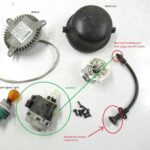
Figure 2: EGR Test using Bi-Directional Controls on Teradyne Pocket Tester for Honda Civic.
Figure 2 displays screen captures from the Teradyne Pocket Tester during an EGR test. Box 1 highlights the “EGR Test” within the Inspection Menu. The red-circled information box provides details about the test. Box 2 presents crucial test instructions. Box 3 shows the test initiation. Box 4 instructs increasing engine speed to 2500-3000 rpm. Box 5 shows live data, including the EGR Lift Sensor bar graph, suggesting the EGR valve is currently functioning. Box 6 displays the test result: “System Normal.” If intermittent sticking is suspected, repeating the test can help confirm the issue. A failed subsequent test would then direct further investigation and potential EGR valve replacement.
In another case, a 1995 Dodge Stratus with an illuminated MIL presented a P0443 – Evap Purge Solenoid Circuit DTC. Diagnostic information indicated that factory DRB III scan tools, as well as aftermarket tools like the Vetronix Mastertech and Snap-on Scanner, could command the purge solenoid.
Figure 3: Evap Purge Solenoid Test using Bi-Directional Controls on Vetronix Mastertech 3100 for Dodge Stratus.
Figure 3 displays screen captures from the Vetronix Mastertech 3100. Box 1 shows the “F6: Purge Test” option. Box 2 allows selecting “F1: Flow” to command purge flow. Box 3 suggests a visual inspection of vacuum lines – a crucial reminder that visual checks often yield quick diagnoses. Box 4 explains scan tool arrow key control of the solenoid. Box 5 shows initial Long Term Adaptive Fuel Trim values.
Commanding the purge valve open should alter fuel trim based on vapor presence in the tank. Rich vapors will decrease fuel trim, while oxygen will increase it. Box 6 shows the purge valve commanded on. Initially, no fuel trim change occurred, suggesting a sticking solenoid. Cycling the valve multiple times eventually resulted in increased fuel trim on the third attempt, indicating the solenoid finally opened. This bi-directional test pinpointed the need for purge solenoid replacement.
A 2004 Toyota Camry with illuminated SRS and Passenger Air Bag lights, referred by a body shop post-accident repair, presented another scenario. Accessing the SRS system required a Mastertech with Toyota software, highlighting the need for appropriate tool and software coverage. DTC retrieval revealed B1782 – Occupant Classification Sensor Rear LH Circuit Malfunction. Visual inspection, guided by diagnostic information, quickly revealed a disconnected Rear LH sensor connector.
Figure 4: Accessing SRS Controller Options and Sensor Data on Mastertech for Toyota Camry.
Figures 4-6 show screen captures from the Mastertech during SRS diagnostics. Figure 4, Box 2 displays controller options. After reconnecting the sensor, sensor data was checked (Box 3). Box 4 shows sensor readings, with weights ranging from 5.50 to 6.60 lbs. Diagnostic charts recommended Zero Calibration after seat replacement.
Figure 5: Zero Calibration Procedure for Occupant Classification Sensors on Toyota Camry.
Figure 5 illustrates Zero Calibration screens. Box 1 highlights “Zero Calibration” as option 5. Boxes 2 and 3 provide specific pre-test instructions. Box 4 confirms completion and recommends a Sensitivity Check.
Figure 6: Sensitivity Check and Weight Verification for Occupant Classification Sensors on Toyota Camry.
Figure 6 shows Sensitivity Check screens. Box 1 highlights “Sensitivity Check” as option 6. Box 2 gives test initiation instructions. Box 3 shows the initial sensor reading of 0.00 lbs., passing the 7 to 7 lbs. test. Box 4 instructs placing 66 lbs. on the seat. Box 5 shows 65 lbs. of weights (50, 10, and 5 lbs.) applied. Box 6 displays a sensor reading of 66.00 lbs., within the 59-73 lbs. range. This SRS repair, including calibration and sensitivity check, would have been impossible without bi-directional control capabilities, OEM software, and specialized tools like a weight set.
Limitations of Bi-Directional Control
These examples showcase the versatility of bi-directional controls. Scan tools often provide helpful information on test procedures and actuation steps. However, situations can arise where bi-directional controls malfunction or behave unexpectedly. Figure 7 illustrates such a scenario with combined screen captures from EASE Diagnostics and Vetronix scan tools.
Figure 7: Inconsistent Bi-Directional Control Information between Scan Tools.
The EASE Chrysler Enhanced software (Figure 7, top left) indicates a purge solenoid cycling on/off every 1.5 seconds with a seven-minute timeout. However, Vetronix Mastertech screen captures (Figure 7, bottom right) from a 1995 Dodge Stratus show the solenoid turning off after approximately 30 seconds (Time Off at 3:53:32 p.m.) after being commanded on (Time On at 3:52:59 p.m.). This automatic shut-off is a safety feature to protect the solenoid. Depending on the component and test, the solenoid might reactivate after a delay.
This example highlights potential inaccuracies in scan tool information. While not ideal, it didn’t prevent diagnosis. A basic understanding of the test’s function (opening and closing the purge solenoid) was sufficient. Ideally, information would be perfectly accurate, but scan tool design specifications are often finalized before production vehicles are released. Vehicle engineers may make subsequent changes, including PCM reprogramming, that aren’t reflected in initial scan tool specifications.
The depth and breadth of bi-directional controls are vast and constantly expanding. To illustrate this, consider the GM Tech 2. GM provides “Tech 2 Pathing Tables,” a set of documents detailing bi-directional functions. These tables, categorized by Body, Powertrain, and Chassis, span 14 pages and list over 1300 tests alphabetically! These documents, available from ACDelco (acdelcotds.com/store) as Part No. ROM00190 for $25, are invaluable for Tech 2 users. A handy pocket reference card is also available (Part No. ROM00164).
For example, to test a malfunctioning electric mirror on a GM vehicle using a Tech 2, the Body Pathing Table can quickly locate the relevant tests. Searching for “Driver’s Electric Mirror” leads to: Body-Memory Mirror Module-Special Functions-Output Controls, where mirror Down/Left/Right/Up commands are accessible.
Other intriguing function tests include Incandescent Dimming, Microphone Test, Military or Standard Time, Phone Call Test/OnStar, and Theater Dimming. And this is just for one OEM and one factory scan tool. Extrapolate this across numerous manufacturers, and the immense diagnostic power of scan tools becomes evident.
In today’s automotive landscape, limiting oneself to older vehicles and basic engine control diagnostics is increasingly unsustainable. Investing in advanced scan tools with comprehensive bi-directional function capabilities is becoming essential. The diagnostic efficiency and accuracy gains offered by these tools will far outweigh their cost in the long run, ensuring technicians are equipped for the complexities of modern vehicle systems.