This guide provides a detailed walkthrough of calibrating a Cummins turbo actuator using an Arduino, a CAN bus shield, and readily available software. This method offers a cost-effective solution to potentially expensive turbo replacements, often recommended by repair shops when faced with specific Cummins turbo error codes.
Understanding the Problem and Solution
Cummins turbo diesel engines often utilize an electronic actuator to control the variable geometry turbocharger (VGT). Malfunctions in this system can trigger diagnostic trouble codes (DTCs) such as U010C (Lost Communication with ECM/PCM) and P003A (Turbocharger/Supercharger Boost Control Position Sensor Circuit). While these codes might suggest a complete turbo failure, the issue often lies with the actuator itself. Replacing the entire turbocharger assembly can be unnecessarily expensive. This guide outlines a DIY approach to calibrate the actuator using an Arduino-based solution, potentially resolving the issue without a costly replacement. This method leverages the CAN bus communication protocol used by the engine control module (ECM) to interface with the actuator.
Gathering the Necessary Tools and Components
Before starting the calibration process, gather the following items:
- Cummins Remanufactured Actuator: Sourcing a remanufactured actuator from a reputable supplier ensures quality and often includes necessary gaskets, hardware, and an alignment pin.
- Arduino Uno or Similar: This microcontroller board will serve as the interface between your computer and the actuator.
- CAN Bus Shield: This shield provides the necessary circuitry for the Arduino to communicate over the CAN bus.
- Connector with Pins: A compatible connector with appropriate pins is crucial for establishing a secure connection to the actuator. Sourcing the correct connector beforehand simplifies the process significantly. Consider obtaining this from the same supplier as the actuator.
- Computer with Arduino IDE: You’ll need a computer with the Arduino Integrated Development Environment (IDE) installed to upload the calibration code to the Arduino.
- Software and Code: Download the necessary software and code for controlling the actuator via the CAN bus. Reliable resources for this software often include specific instructions for setup and usage.
- Basic Tools: Standard hand tools, including sockets, wrenches, and screwdrivers, will be required for disassembly and reassembly.
- CRC Intake Valve Cleaner: This will be used to clean the turbocharger components.
- 5-Gallon Bucket: For draining coolant.
- Allen Wrench or Drill Bit: For aligning the VGT lever.
Step-by-Step Calibration Process
-
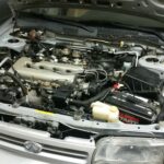
Preparation: Disconnect the negative battery terminal. For easier access to the turbocharger, remove the passenger-side inner fender well. Drain the engine coolant into a 5-gallon bucket by disconnecting the lower radiator hose.
-
Actuator Removal and Cleaning: Detach the actuator from the turbocharger. This is usually a straightforward process involving a few bolts. With the actuator removed, detach the turbo downpipe to access the turbine housing. Clean the variable vanes and the turbine wheel using CRC Intake Valve Cleaner. Ensure the VGT lever moves freely. Clean the mating surface of the turbocharger where the actuator mounts.
-
Arduino Setup: Download the necessary Arduino code and CAN bus library. Install the CAN bus library in the Arduino IDE. Connect the CAN bus shield to the Arduino. Modify the code if necessary to specify the correct CAN bus shield pin. Connect the actuator to the Arduino using the connector and appropriate wiring.
-
Initial Calibration: Connect the Arduino to your computer via USB. Upload the calibration code to the Arduino. Connect the actuator to a power source and ground on the truck battery. Run the first calibration step. This initializes the actuator. Disconnect power and then the USB connection.
-
VGT Lever Alignment: Align the VGT lever on the turbocharger using an allen wrench or drill bit, ensuring it sits in the designated alignment hole. Apply the supplied grease to the lever teeth. Install the new actuator.
-
Final Calibration: Reconnect the Arduino, power, and ground to the actuator. Run the second calibration step. This process will move the actuator through its full range of motion, setting the limits and parking position. Disconnect power and then the USB.
-
Reassembly: Reinstall the downpipe, inner fender, and reconnect the lower radiator hose. Refill the cooling system. Reconnect the negative battery terminal.
Verification and Conclusion
After completing these steps, start the engine and monitor for any error codes. Verify that the exhaust brake (EB) and boost pressure function correctly. Successful calibration should restore proper turbo operation, eliminating the initial error codes and performance issues. This DIY method can save significant cost and time compared to replacing the entire turbocharger. Remember to consult your vehicle’s specific repair manual for detailed instructions and torque specifications.
-
Arduino IDE with code uploaded and ready for actuator calibration. Note the selected port and board configuration.
-
Cummins turbo actuator connected to the Arduino via a CAN bus shield and custom wiring harness. This setup enables direct communication for calibration.
-
Close-up view of the variable geometry turbo (VGT) lever and alignment hole. Precise alignment is critical for proper actuator function and turbocharger performance. An allen wrench is used for alignment in this image.