Understanding the diagnostic systems in your 1996 Plymouth Grand Voyager is crucial for maintaining its reliability and performance. While modern vehicles heavily rely on sophisticated scan tools, the 1996 Grand Voyager offers a blend of onboard diagnostics and compatibility with early scan tools. This guide delves into interpreting diagnostic codes and troubleshooting common issues, particularly focusing on how a scan tool can assist in diagnosing your vehicle.
The original query from a user experiencing flashing lights and error codes provides a perfect starting point. The described symptoms – flashing lights on the heater panel and specific flash codes – are indicative of the Voyager’s self-diagnostic capabilities. Let’s break down these codes and explore how to effectively diagnose and address them.
Decoding Flash Codes on a 1996 Plymouth Grand Voyager
The user reported a series of flash codes: 1-2, 3-2, and 4-1. These are indeed diagnostic trouble codes (DTCs) communicated through the vehicle’s system. Here’s a breakdown of what these codes mean for a 1996 Plymouth Grand Voyager:
-
Code 12 (1 flash – pause – 2 flashes): Battery Disconnected Recently. This is often considered an informational code. It indicates that the battery has been disconnected within the last 50 engine start cycles. It’s generally not a cause for concern and doesn’t typically illuminate the Service Engine Soon (SES) light. Think of it as a system memory reset. If you’ve recently worked on your car or had the battery disconnected for any reason, this code is likely normal. It’s more of a “nuisance code” as mentioned, rather than a critical fault.
-
Code 32 (3 flashes – pause – 2 flashes): EGR Solenoid Circuit Fault. This code points to a problem within the Exhaust Gas Recirculation (EGR) system, specifically the solenoid circuit. The EGR system is vital for reducing NOx emissions by recirculating a portion of the exhaust gas back into the intake manifold. A fault in the solenoid circuit could mean a wiring issue, a malfunctioning solenoid, or a problem with the EGR valve itself. Modern OBD-II scan tools would likely translate this to a P0403 code, as referenced, which further confirms an EGR solenoid circuit malfunction. Addressing this code is important for both emissions compliance and engine performance.
-
Code 41 (4 flashes – pause – 1 flash): Alternator Field Not Switching. This is a more serious code indicating a problem with the alternator’s field circuit. The alternator is responsible for charging the battery and powering the electrical system while the engine is running. “Alternator field not switching” suggests that the alternator might not be properly regulating its output, potentially leading to undercharging or overcharging of the battery. As suggested, you should be seeing the battery warning light illuminated on the dashboard with this code. It’s crucial to have the charging system tested immediately. Most auto parts stores offer free charging system tests to pinpoint whether the alternator, battery, or related wiring is at fault.
Resetting Codes and Further Diagnosis
The first recommended step is to reset the diagnostic codes. This is easily done by disconnecting the negative battery cable for a couple of minutes. This clears the vehicle’s computer memory. After reconnecting the battery, operate the vehicle and see which codes, if any, reappear. This helps determine if the codes were transient or represent persistent issues.
If the codes return, especially codes 32 and 41, further investigation is necessary. For code 32, check the wiring to the EGR solenoid for damage or corrosion. Test the solenoid itself for proper function. For code 41, a thorough charging system test is essential. This test will evaluate the alternator’s output voltage and current, as well as the battery’s condition.
Utilizing a Scan Tool for a 1996 Plymouth Grand Voyager
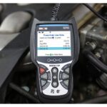
While the flashing light method provides basic diagnostic information, a scan tool offers a more in-depth and user-friendly approach. For a 1996 Plymouth Grand Voyager, you would typically use an OBD-I scan tool compatible with Chrysler vehicles of that era. These scan tools can:
- Read Diagnostic Trouble Codes (DTCs) in a clearer format: Instead of counting flashes, the scan tool displays the codes numerically (like 12, 32, 41) and often provides a brief description.
- Offer Live Data Streaming: More advanced OBD-I scan tools can display live engine parameters such as sensor readings, engine temperature, and RPM. This real-time data can be invaluable for diagnosing intermittent issues or verifying sensor functionality related to codes like EGR or alternator faults.
- Perform Actuator Tests: Some scan tools may offer limited actuator tests for systems like the EGR, allowing you to command the solenoid to activate and verify its response.
While a generic OBD-II scan tool is not directly compatible with the 1996 Grand Voyager’s OBD-I system without an adapter (and even then, functionality might be limited), using a proper OBD-I Chrysler scan tool or a professional-grade scan tool with OBD-I capabilities can significantly streamline the diagnostic process.
HVAC Diagnostic Flashing Lights
Beyond engine codes, the flashing lights on the heater panel in the original query indicate a separate HVAC (Heating, Ventilation, and Air Conditioning) diagnostic system. The simultaneous flashing of the Rear Wiper and Rear Intermittent switch lights suggests that the HVAC control module has detected a fault or requires calibration.
The provided text details a comprehensive HVAC diagnostic and calibration procedure. Here’s a simplified breakdown:
HVAC Actuator Calibration/Diagnostics and Cooldown Test:
This procedure is crucial, especially if the HVAC control module has been replaced or if you suspect issues with the system’s actuators (motors that control air doors).
Entering Calibration/Diagnostics Test Mode:
- Set Blower Fan: Turn the blower motor to the HIGH setting.
- Mode Position: Select PANEL mode to open all A/C outlets.
- Temperature: Set the temperature to COLD (using both slide pots if equipped for dual-zone systems).
- Initiate Test: Simultaneously press and hold the WASH and REAR WIPER buttons for 5 seconds until all LEDs light up.
Interpreting LED Flashes during HVAC Diagnostics:
- All LEDs light for 5 seconds: This indicates the test initiation was successful.
- Rear Wiper and Intermittent LEDs alternately flashing: Calibration test is running.
- A/C and Recirc LEDs alternately flashing: Cooldown test is running (if applicable to your model with A/C).
Pass/Fail LED Codes After HVAC Diagnostics:
- No LEDs Flashing (Normal Operation): Calibration, Diagnostics, and Cooldown tests passed. No faults detected.
- Rear Wiper and Intermittent LEDs flashing simultaneously: Calibration Diagnostics failed. Run the calibration test again.
- A/C and Recirc LEDs flashing simultaneously: Cooldown test failed. Run the cooldown test.
- Rear Wiper and Intermittent LEDs AND A/C and Recirc LEDs flashing simultaneously: Both Calibration Diagnostics and Cooldown tests failed. Run the calibration test.
Exiting HVAC Diagnostic Mode:
- Press the Rear Wiper button to exit after successful tests.
HVAC Fail Codes:
If the calibration/diagnostic test fails, the system will display fail codes using the Rear Wiper (Level) and Intermittent (Value) LEDs. By pressing the WASH button, you can cycle through different levels of diagnostic information, including specific actuator failure codes and potentiometer tests. Refer to the provided table in the original text for detailed fail code interpretations.
Troubleshooting HVAC Issues:
If the HVAC system fails calibration or displays error codes, common issues can include:
- Actuator Malfunctions: The actuators themselves can fail, become stuck, or lose calibration.
- Wiring Problems: Check wiring and connectors to the actuators and HVAC control module for damage, corrosion, or loose connections.
- Control Module Fault: In some cases, the HVAC control module itself may be faulty.
Cooldown Test (A/C Performance):
The cooldown test is specifically for evaluating the A/C system’s performance. It checks if the system can bring the evaporator temperature down to a specified level within two minutes. To initiate the cooldown test separately, follow a similar procedure but press the WASH and A/C buttons instead of WASH and REAR WIPER.
Conclusion
Diagnosing a 1996 Plymouth Grand Voyager involves understanding both its engine management system and its separate HVAC diagnostics. While flash codes provide a basic level of troubleshooting, utilizing a compatible OBD-I scan tool can significantly enhance the diagnostic process, especially for engine-related issues. For HVAC problems, the onboard self-diagnostic and calibration procedures, indicated by flashing LEDs, are invaluable. By carefully interpreting these codes and following the outlined procedures, you can effectively diagnose and address many common issues in your 1996 Plymouth Grand Voyager, ensuring its continued reliable operation. Remember to always consult repair manuals and wiring diagrams for detailed troubleshooting and repair information.