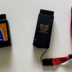
A Vcds Actuator Test is a crucial step in diagnosing turbocharger problems in Volkswagen, Audi, Seat, and Skoda vehicles. This article outlines a real-world troubleshooting scenario using VCDS (Vag-Com Diagnostic System) to pinpoint the root cause of a turbocharger malfunction. We’ll delve into the process of conducting an actuator test, interpreting the results, and the importance of understanding measuring block data.
Understanding the VCDS Actuator Test
The VCDS software allows users to perform output tests on various components, including the turbocharger actuator. This test cycles the actuator through its range of motion, allowing for visual inspection of movement and identification of potential sticking or binding issues. Coupled with measuring block readings, this provides valuable diagnostic information. This case study highlights the use of output tests in conjunction with measuring block 120 to assess actuator voltage with and without vacuum.
Case Study: Troubleshooting a Turbocharger Malfunction with VCDS
The initial diagnosis began with checking fuses and confirming voltage at the actuator using a multimeter. Discrepancies in voltage readings between pins on the actuator connector suggested a potential problem. Resistance measurements of the actuator were then taken and compared to a bench test of the original actuator, revealing possible internal issues.
Further investigation focused on the charge hoses. A pressure test revealed a leak in the intercooler hose, which was subsequently repaired. Despite this fix, the turbocharger continued to exhibit issues, indicated by a flashing glow plug light (GPL) during subsequent VCDS output tests. Although the actuator showed movement for a few cycles, the vehicle eventually entered limp mode.
Utilizing Measuring Block 120 for Accurate Diagnosis
Following the Ross-Tech guide, measuring block 120 was used to monitor the actuator voltage. With no vacuum applied, the reading should fall between 3.30V and 3.90V. Initial readings were slightly below this range, prompting an adjustment to the actuator rod. This adjustment brought the voltage within the specified range. Under vacuum, the rod movement and corresponding voltage readings aligned with expected values.
VCDS Scan Results and Interpretation
Despite the repairs and adjustments, a VCDS scan revealed persistent fault codes:
- 000175 – Actuator Module for Turbocharger 1 (P00AF) – Stuck: This code indicates a mechanical issue with the actuator itself, suggesting it’s unable to move freely.
- 009571 – Turbocharger Boost Control Position Sensor Circuit (P2563) – Implausible Signal: This code points to an inconsistency between the expected and actual position of the actuator, potentially due to a faulty sensor or wiring issue.
The scan also provided detailed information about the engine controller, ABS brakes, HVAC system, and other modules, confirming their proper functionality.
Conclusion: Pinpointing the Problem with VCDS
Through the use of the VCDS actuator test, measuring block data analysis, and fault code interpretation, the troubleshooting process narrowed down the problem to the turbocharger actuator itself. While the intercooler hose leak was a contributing factor, the persistent fault codes and actuator behavior point to a more significant issue within the turbocharger actuator requiring further attention or replacement. This case study demonstrates the power of VCDS as a diagnostic tool for effectively identifying and resolving complex automotive problems.

