
Rear view cameras significantly improve safety and parking ease. This guide focuses on retrofitting a low-line rear view camera in MQB platform vehicles using VCDS coding. Understanding the difference between high-line and low-line cameras is crucial for a successful installation.
High-Line vs. Low-Line Rear View Cameras
MQB platform cars utilize two main types of rear view cameras: high-line and low-line. High-line cameras are intelligent devices, functioning as independent units within the CAN network. They communicate directly with the car’s systems through their own control modules (address hex6C). Conversely, low-line cameras are simpler devices that rely on the MIB unit (infotainment system, address hex5F) for processing and display.
Low-Line Camera Installation and VCDS Coding
Low-line cameras connect to the MIB unit via a coaxial cable, utilizing a quad-connector at the rear of the MIB (J794). 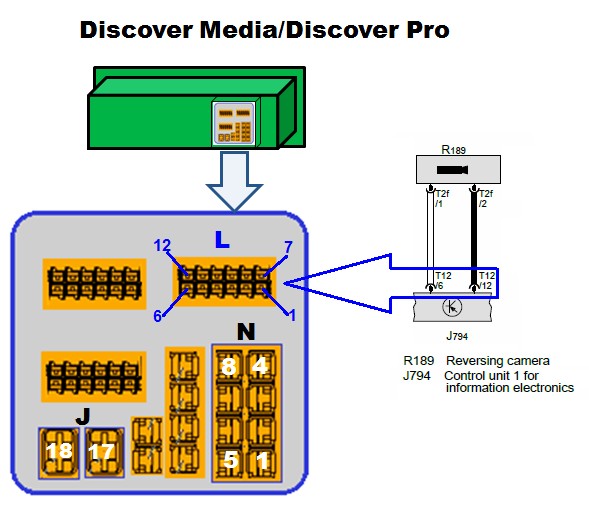 MIB unit with coaxial cable connection for low-line rear view camera. Both camera types use a voltage signal from the reversing light to trigger activation.
This guide assumes you’re retrofitting a low-line camera. This requires enabling the camera functionality within the MIB unit using VCDS. The specific setting resides within the hex5F module’s long coding.
Modifying the Hex5F Long Coding
The software switch for a low-line camera is located in Byte 19, Bit 4 of the hex5F long coding.
In the provided auto-scans, Byte 19 is hexC6, which translates to binary 1100 0110. Remember, binary is read right-to-left. Bit 4 (the fifth digit from the right) is currently set to 0. This indicates that the MIB is not configured for a rear view camera.
To enable the camera, change Bit 4 of Byte 19 to 1. This changes Byte 19 to hexD6.
The complete long coding string for the MIB unit before and after the modification is:
- Before: 02840201FF00000051111101008808001F0100C601200100CF
- After: 02840201FF00000051111101008808001F0100D601200100CF
Hex10 Module Check
Another setting, Byte 2, Bit 4 in module hex10, is usually required for rear view camera functionality. However, the provided auto-scans indicate this is already enabled.
Conclusion
After completing the physical installation of the low-line camera, modify the hex5F long coding as outlined above. This enables the MIB unit to recognize and operate the newly installed camera. Ensure the hex10 setting is also enabled, though it likely already is based on the provided data. With these changes, your retrofitted low-line rear view camera should function correctly.