
Vcds Optical Bus Diagnostics, while not directly supported in VCDS software, can be performed using some clever techniques. The MOST (Media Oriented Systems Transport) bus in many Audi vehicles uses a fiber optic ring topology for communication between various modules like the radio, navigation, and amplifier. A break in this ring can lead to a variety of issues. This article explores how to troubleshoot and diagnose these problems.
Understanding the MOST Bus Ring Topology
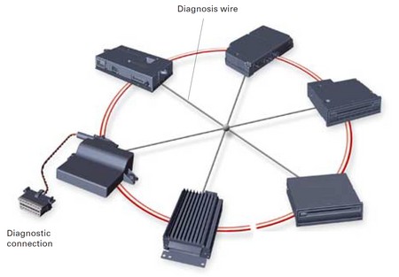
The MOST bus operates on a ring structure where data is passed sequentially from one module to the next. Each module receives data, processes it, and then transmits it to the next module in the ring. This continuous loop ensures seamless communication. If one module fails or a cable is damaged, the entire ring is disrupted. Visualize it as a circle: if you break the circle at any point, the connection is lost.
This ring topology means that a single point of failure can bring down the entire system. Therefore, effective diagnostic techniques are crucial for identifying the source of the problem. While VCDS doesn’t have a dedicated optical diagnostic function, we can still leverage its capabilities along with other tools.
Utilizing the Audi Fiber Optic Bypass Loop
One effective method for vcds optical bus diagnostics involves using a specialized tool: the Audi fiber optic bypass loop (part number 4E0 973 802). This loop essentially bypasses a suspected faulty module, allowing you to test whether that module is causing the communication breakdown.
To use the bypass loop:
- Disconnect the MOST connectors from the suspected faulty module.
- Plug the bypass loop into the connectors, effectively removing the module from the ring.
- Observe if communication is restored on the remaining modules. If communication resumes, the bypassed module is likely the culprit.
By systematically bypassing each module, you can pinpoint the source of the problem. Remember to reconnect each module after testing to maintain the integrity of the system. This manual method provides a practical approach to vcds optical bus diagnostics.
Exploring Electrical Fault Diagnostics with VCDS
While optical issues are possible (damaged cables, faulty connectors), electrical faults within the MOST ring are more common. The MOST bus also incorporates a ring break diagnostic wire system. VCDS can be used to troubleshoot these electrical issues.
Within VCDS, navigate to the “Live Data” function of the relevant module. Look for the “Start ring break diagnostics” option. Initiating this procedure will trigger a diagnostic test within the module itself, checking for electrical continuity and signaling issues. This built-in functionality provides a valuable resource for vcds optical bus diagnostics, addressing the electrical aspect of the MOST system.
While physical damage to fiber optic cables is less frequent, it’s still a possibility. Inspect the cables carefully for any signs of breakage, bending, or damage to the connectors. Often, a careful visual inspection can reveal obvious physical issues. Combine this with the bypass loop technique and the electrical diagnostics provided within VCDS for a comprehensive diagnostic approach.