When your 6.0L diesel engine refuses to start, or runsRoughly, or stalls unexpectedly, it can be a frustrating experience. Often, these issues are intertwined with the engine’s complex electronic control systems, particularly the Fuel Injection Control Module (FICM). A common question among diesel mechanics and enthusiasts alike is: do FICMs have to be checked with a scan tool?
This article, brought to you by the experts at vcdstool.com, will delve into diagnosing crank no-start conditions in 6.0L diesels, focusing on the crucial role of scan tools in assessing FICM and related systems. We’ll explore how reading key diagnostic codes and using tools like oscilloscopes and DVOMs (Digital Volt-Ohm Meters) can pinpoint problems and get your engine back in action.
Understanding SYNC and FICMSYNC: The Heartbeat of Your Diesel
Before we jump into diagnostics, it’s essential to understand two critical parameters: SYNC and FICMSYNC. These are diagnostic PIDs (Parameter IDs) that can be monitored using a scan tool and provide vital clues about the engine’s health.
-
SYNC PID: This indicates whether the PCM (Powertrain Control Module) is synchronized with the signals from both the CKP (Crankshaft Position) and CMP (Camshaft Position) sensors. For the engine to start and run correctly, the PCM needs to know the positions of the crankshaft and camshaft. A “SYNC Yes” reading means these signals are properly aligned and recognized by the PCM.
-
FICMSYNC PID: This parameter shows if the FICM is synchronized with the CKPO (Crankshaft Position Output) and CMPO (Camshaft Position Output) signals from the PCM. The FICM relies on these signals to precisely control fuel injection timing. “FICMSYNC Yes” signifies that the FICM is correctly receiving and interpreting these signals.
When troubleshooting a no-start condition, examining these PIDs with a scan tool is often the first crucial step.
Symptoms Indicating SYNC or FICMSYNC Problems
Loss of SYNC or FICMSYNC, or erratic readings from these parameters, can manifest in various symptoms, including:
- Crank No Start with SYNC No and FICMSYNC No: This scenario suggests a fundamental issue with the crankshaft and/or camshaft position sensor signals reaching both the PCM and FICM.
- Crank No Start with SYNC Yes and FICMSYNC No: Here, the PCM is synchronized, indicating the CKP and CMP sensors are likely functioning correctly. However, the FICM is not synchronized, pointing to a potential problem in the communication between the PCM and FICM, or within the FICM itself.
- Crank No Start with SYNC No and FICMSYNC Yes: This is a less common situation where the FICM is synchronized but the PCM is not. It could indicate issues primarily affecting the PCM’s ability to read the CKP and CMP sensors.
- Crank No Start with Erratic SYNC or FICMSYNC Switching from No to Yes: Intermittent signal issues can cause these parameters to fluctuate, often leading to starting problems.
- Vehicle Stalling, Running Rough, or Missing with SYNC or FICMSYNC Switching from Yes to No: If the SYNC or FICMSYNC signals drop out while the engine is running, it can cause misfires, rough running, or stalling.
For any of these symptoms, a systematic diagnostic approach is necessary, starting with reading fault codes and monitoring SYNC and FICMSYNC PIDs using a scan tool.
Possible Causes Behind SYNC and FICMSYNC Loss
Several factors can lead to a loss of SYNC or FICMSYNC. These can be broadly categorized into sensor issues, wiring problems, module failures, and mechanical faults:
- Faulty Cam Sensor: A failing camshaft position sensor can prevent the PCM from achieving SYNC.
- Faulty Crank Sensor: Similarly, a malfunctioning crankshaft position sensor disrupts the PCM’s ability to synchronize.
- Signal Shorts or Opens: Wiring issues such as shorts to power or ground, or open circuits in the sensor or signal wiring, can interrupt signal transmission.
- PCM Malfunction: In some cases, the PCM itself might be the source of the problem, failing to process sensor signals correctly.
- FICM Issues: A faulty FICM might not be able to synchronize even if it receives signals from the PCM, or it might fail to communicate correctly with the PCM.
- Cam Gear or Pin Problems: Mechanical issues like a damaged or loose cam gear or pin can disrupt the camshaft position signal.
- Crankshaft Tone Wheel Damage: Damage or looseness of the crankshaft tone wheel, which the CKP sensor reads, can lead to erratic or absent CKP signals.
It’s important to note that the RPM PID (Revolutions Per Minute) on a scan tool can sometimes offer a quick initial clue. Erratic RPM readings during cranking can suggest a wobbly or loose CKP tone wheel.
Diagnostic Procedures: Scan Tools, Oscilloscopes, and DVOMs
Diagnosing SYNC and FICMSYNC issues requires a methodical approach, often involving a combination of diagnostic tools.
1. Initial Scan Tool Assessment
The first step should always be to use a scan tool to:
- Read Diagnostic Trouble Codes (DTCs): Check for any stored codes related to the cam or crank sensors (e.g., P2614, P2617). These codes can provide an initial direction for your diagnosis.
- Monitor SYNC and FICMSYNC PIDs: Observe these parameters while cranking the engine. Are they reading “Yes” or “No”? Are they erratic? This real-time data is crucial for understanding the nature of the problem.
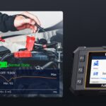
Answering the Key Question: Do FICMs Have to Be Checked with a Scan Tool?
Yes, absolutely. A scan tool is indispensable for initially checking FICMSYNC and SYNC PIDs. Without it, you’d be working in the dark, guessing at the root cause. The scan tool provides the essential first layer of diagnostic information, telling you whether the FICM synchronization is the issue and guiding your subsequent steps.
2. Oscilloscope Diagnostics: Deep Dive into Signal Waveforms
For a more in-depth analysis, especially when dealing with erratic signals or suspecting signal integrity issues, an oscilloscope is the preferred tool. An oscilloscope allows you to visualize the waveforms of the CKP, CMP, CKPO, and CMPO signals, providing a detailed picture of their quality and timing.
Alt Text: Oscilloscope display showing typical CKP (Crankshaft Position) and CMP (Camshaft Position) signal waveforms for a 6.0L diesel engine, illustrating proper signal patterns for diagnostic comparison.
Oscilloscope Procedure for CKP and CMP Signals (PCM Input):
- Setup: Connect the oscilloscope to the CKP and CMP signal wires going into the PCM. A Break-Out-Box (BOB) can simplify accessing PCM pins.
- Channel Configuration: Set up oscilloscope channels for CKP and CMP signals (typically using auto-setup for diesel CKP/CMP or manual settings around 5V/div and 20ms/div).
- Trigger: Use a “One Shot” trigger mode to capture the waveforms during cranking.
- Waveform Analysis: Compare the captured waveforms to known good patterns. Look for:
- Signal Presence: Is there a signal at all?
- Signal Amplitude: Is the signal voltage within the expected range?
- Signal Pattern: Does the waveform shape look correct (consistent pulses with a missing tooth pattern for CKP)?
- Signal Timing: Are the CKP and CMP signals correctly synchronized relative to each other?
Oscilloscope Procedure for CKPO and CMPO Signals (PCM Output to FICM):
The procedure is similar to CKP/CMP, but you’ll connect the oscilloscope to the CKPO and CMPO signal wires between the PCM and FICM. Analyze these waveforms to ensure the PCM is correctly sending output signals to the FICM.
3. DVOM Diagnostics: A Simpler Approach (When Oscilloscope Isn’t Available)
While an oscilloscope offers the most comprehensive signal analysis, a DVOM can be used for basic checks, especially when an oscilloscope isn’t accessible. However, interpreting DVOM readings for these signals can be less straightforward.
DVOM Procedures for SYNC and FICMSYNC Issues:
- Checking for CKP Signal (SYNC=No, No/Low RPM): Measure the frequency (Hz) and AC voltage on the CKP sensor circuit. A valid frequency reading (around 150-190 Hz while cranking) and a steady AC voltage (at least 0.6V) indicate a likely functioning CKP sensor and circuit.
- Checking for CMP Signal (SYNC=No, RPM Present): Measure the frequency and AC voltage on the CMP sensor circuit. A valid frequency (around 1.1-1.6 Hz) and fluctuating AC voltage (going over 1V) suggest a working CMP sensor and circuit.
- Checking CKPO and CMPO Signals (SYNC=Yes, FICMSYNC=No): Backprobe the CKPO and CMPO pins at both the PCM and FICM connectors. Measure the frequency at these points while cranking. The readings should be consistent between the PCM and FICM. Discrepancies indicate wiring issues, while absent signals at both ends might point to PCM or FICM output problems.
Important Notes on DVOM Use:
- DVOM readings for CMP signals will fluctuate significantly due to the camshaft rotating at half crankshaft speed and having only one timing peg per two revolutions.
- DVOM is less accurate than an oscilloscope for diagnosing signal integrity and timing issues. It’s best used for basic signal presence and frequency checks.
Mechanical Timing Considerations
If all electrical tests pass and FICMSYNC issues persist, mechanical timing problems should be considered. These can include:
- Slipped Crankshaft Tone Ring: A loose or damaged tone ring can cause erratic CKP signals and FICMSYNC errors.
- Loose Camshaft Gear or Pin: Mechanical looseness in the camshaft drive components can lead to timing misalignment and FICMSYNC problems.
These mechanical issues often require more invasive inspection, potentially including oil pan removal to check the crankshaft tone wheel or valve cover removal to inspect the camshaft gear.
Conclusion: Scan Tools – Your First Line of Defense
Diagnosing crank no-start conditions in 6.0L diesel engines effectively begins with a scan tool. Monitoring SYNC and FICMSYNC PIDs provides immediate insights into the synchronization status of the PCM and FICM, guiding you towards the potential problem area. While oscilloscopes and DVOMs offer deeper levels of diagnostics, the scan tool is your essential first step.
Remember to always follow a systematic diagnostic approach, starting with the basics and progressing to more advanced techniques as needed. And for reliable diagnostic tools and further resources, visit vcdstool.com, your partner in automotive diagnostics.